06.11.2025
Knowing, understanding and using pullers: the separation assembly
Inhalt
There are many types of pullers. External pullers are used to remove parts that sit on a shaft. Internal pullers can be used to lift components that are difficult to access in a recess. But what are separation assemblies for? How are they made and how are they used? Read this article to find out.
As with all pullers, separation assemblies are designed to release jammed components safely and in a controlled manner. They are used when a component part - for example a bearing, a pulley or an inner ring - lies particularly firmly and flat on the surface. In other words, in cases where the hooks of a conventional external puller cannot reach under the component.
01.
How is a separation assembly constructed?
A commercially available separation assembly set consists of a separation assembly for the separation process and a puller for pulling off the component. For the sake of simplicity, let’s take a closer look at both devices.
These parts form part of the separation assembly:
- Cutting devices, claws or jaws: These are two pointed metal discs. They give their name to the separation assembly (separator) and work like a wedge that slides under the component to be removed from two sides. Each cutting edge also has an internal thread accessible from above.
- Side bolts or screws: To press the arms synchronously under the part, the arms are connected to each other by two parallel screws: one on each side of the shaft on which the part to be pulled is seated. Nuts on the side bolts move the cutting devices together.
These parts are part of the puller:
- Beam: This is screwed onto the tension bolt before pulling off.
- Tension bolts: They have a thread on each side which is required for screwing into the separation assembly and as a screw connection to the beam.
- Spindle screw: It runs centrally through the beam and is in contact with the shaft during the pulling process.
02.
How to use a separation assembly correctly:
A separation assembly is not difficult to use. Here’s a quick guide for you:
- Step 1: First, you have to place one blade on each side of the part to be removed. Then connect the arms together by establishing the horizontal bolt connections with the side bolts by hand.
- Step 2: Now it’s time for the actual separation. Always tighten the screws alternately a few turns so that the arms slide evenly under the component from both sides like a wedge. Continue tightening until the stop is reached.
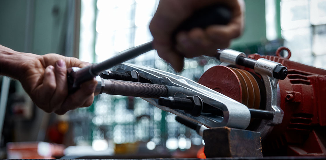
- Step 3: Now attach the puller. Screw the tension bolts to the vertical internal threads of the arms. Then screw in the spindle screw of the puller by hand in a clockwise direction until it rests on the shaft.
- Step 4: Now all you have to do is turn the spindle screw of the beam further clockwise using a spanner. The physics here are the same as for the external puller: The spindle exerts a compression force on the shaft, the bolts exert a pulling force on the arms. The arms are lifted and thus move the part being removed upwards.
03.
What types are there?
Different dimensions of arms and pullers are available depending on the type and size of the component. There are also extensions for the extraction bolts: You need this, for example, if the shaft protrudes far and the extraction bolts of your puller are not long enough to achieve the required depth, i.e. to bridge the distance to the component or its surface.
04.
What should be observed when using separation assemblies?
Even when things get hectic: Be sure to observe the following: Otherwise, you risk damaging the tool or components!
- Make sure to select a separation assembly that matches the proportions of the component!
- When separating, always tighten the screws alternately and as evenly as possible. Otherwise tensions and poor force distribution will occur. The tool can tilt, and in the worst case scenario, the component, the screws or the screw threads can be damaged.
- Tighten the separation assembly until the component to be removed is in contact with the stop of the arms on both sides!
- Adjust the distance of the tension bolts exactly to the distance of the threads in the arms. Also make sure that the spindle is centred on the shaft. Uneven alignment may result in poor force distribution and damage to the part to be pulled, the shaft or the puller.
- Always screw the puller’s tension bolts into the arms as far as they will go to ensure a secure connection without play.
- In general: Proceed with due care. If something feels wrong or too stiff, check again if everything is correct!
- Tip: As an alternative to the puller, you can also use a classic 2-arm puller if you have already been able to lift the component with the separator and there is now enough space for the pulling jaws.
Have we piqued your interest? Then these posts might also be for you:
Would you like to get to know the puller range from STAHLWILLE? Click here to see our products:
Company
Service
2026© All Rights Reserved