05.11.2025
Controlled pulling with the external puller
Inhalt
Pullers are part of every professional tool setup. You can find out what advantages they offer and which types are available here: External puller, internal puller, separator: What are they for?
In this article, we will focus on the external puller in detail: How is it structured, how is it applied, which types are available to choose from? Explaining when an external puller is used is simple: whenever a component is firmly seated on a shaft and needs to be removed smoothly and carefully in a controlled manner. But how exactly does it work?
01.
How is an external puller designed?
The basic design of an external puller is relatively simple: It consists of extractor hooks, a beam and a spindle. There are also models that offer various adjustment options - for example with the help of integrated joints.
- The extractor hooks (also called “arms” or “legs”) are mounted on the beam. Their job: To grip the component to be removed. Depending on the version, an external puller has two or three extractor hooks. There are also models with swivelling or self-centering hooks.
- The beam is not only there to hold the extractor hooks. It is also possible to change the position of the extractor hooks. Therefore, the span of the puller can be adjusted to the diameter of the part to be pulled.
- The spindle is a screw with a fine thread that runs through a thread in the centre of the beam. It usually has a tapered tip for centering and a hexagonal spindle head which is used to operate the puller. The task of the spindle is to exert pressure on the shaft and simultaneously build up a pulling force by lifting the beam and extractor hooks.
02.
How is an external puller used?
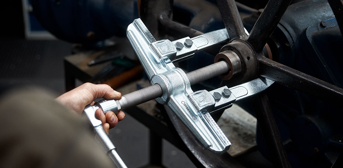
To pull off a component, the extractor hooks of the external puller are first adjusted to the diameter of the part - traditionally a gear or a bearing - and their hooks are positioned under the part to be removed. In the second step, the spindle screw running through the beam is screwed in by hand in a clockwise direction until it lies centrally on the shaft.
Only then does the actual pulling take place: Use a spanner to turn the spindle clockwise again. The rest is physics: The spindle exerts downward pressure on the shaft. The beam - and with it the hooks - move upwards due to the spindle rotation, so that a pulling force is built up on the component which counteracts the compressive force.
As this tension force is distributed over several arms of the puller, it acts evenly on the entire component. This raises it without jerking or skewing, preventing damage to the component or the shaft.
03.
What special types of external puller are available?
In contrast to the traditional design described above, two other designs have proven themselves: those with self-centering or swivelling extractor hooks.
- For external pullers with self-centering extractor hooks, both extractor hooks are connected to each other so that they are automatically clamped and centred during the pulling process. This saves the user time and reduces the risk of incorrect positioning. Even load distribution is guaranteed. This makes this type particularly suitable for consistent pulling operations.
- For external pullers with swivelling extractor hooks, the beam and extractor hooks are connected to each other via movable adaptors. The extractor hooks tighten automatically when the spindle is tightened. This design is particularly suitable for narrow installation spaces and is very easy to attach.
- For external pullers with lateral clamping pins, force is applied with an additional lateral spindle. As a result, the extractor hooks are pushed under a component like in a separation device. With this design, the extractor hooks cannot jump off during the pulling process.
04.
What should be observed when using external pullers?
If the external puller is used incorrectly, the tool or the component to be removed can be damaged. Therefore, pay particular attention to these instructions:
- Choose the right model: If there is enough space, it is advisable to insert a 3-arm puller to ensure optimal load distribution. Ideally, 2-arm pullers should only be used in confined installation spaces.
- Choose the right size: Using a puller that is too small or too large can damage the component. Ideally, an external puller should be used with a clamping depth and extractor hook length that can be variably adapted to the application.
- Positioning of the extractor hooks: The extractor hooks must always be completely seated on the beam and must never protrude. The hooks must fit completely under the part to be removed, and they must be straight.
- Centering: With shafts positioned centrally, the puller must also be positioned centrally. If the shaft is positioned asymmetrically, a puller with parallel extractor hooks is required.
- Only one component at a time: If several overlapping components are to be removed, each one must be removed individually. If several parts are “gripped” at the same time, there is a risk of damage.
- Dosing force: Extensions are also unsuitable for increasing the lever travel when operating a puller. Instead, use suitable tools such as a ratchet, spanner or ideally a torque wrench for hydraulic spindles.
- Accident prevention: To protect against sudden movements when pulling, the puller and the part to be pulled should be covered with an accident protection tarpaulin.
Did you like this article? Also read:
Would you like to get to know the puller range from STAHLWILLE? Click here to see our products:
Company
Service
2026© All Rights Reserved